
LL (Low Loss) Coaxial Cables
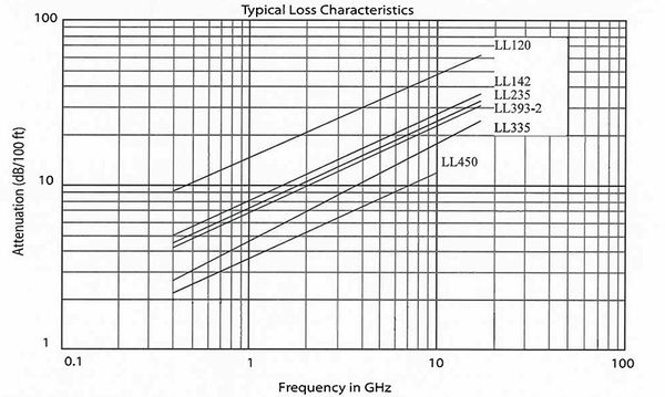
Unique cable design: The braid configuration and the expanded PTFE dielectrics of the LL cable constructions contribute to lower attenuation levels at higher frequencies, while providing shielding effectiveness levels that exceed those of flexible MIL-C-17 cables. Flat strips of silver plated copper are braided over the dielectric core with an intermediate metallized polyester or polyimide layer, and an outer round wire braid. Improved electrical characteristics: LL cables with expanded PTFE dielectrics exhibit low coefficients of expansion over the entire operating temperature range from -100° C to +250° C. Impedance discontinuities are minimized at the cable- to-connector interface. Higher levels of power can be transmitted because higher temperatures do not affect the cable due to the temperature stability of the tape. Where phase versus temperature requirements are critical, LL cables allow for an approximately 75% lower phase shift and change in propagation time delay due to temperature. Temperature cycling tests have been performed on a number of cables with positive results. Lowest attenuation for any given size: LL coaxial cables, with expanded PTFE dielectrics and strip braid composite configurations, offer attenuation from 20 to 35% below other mil spec cables of comparable size. When size and weight are considerations, LL cables should be considered. The graph below defines maximum attenuation levels for all LL cables referenced on the next page. Technical support available: We continually work with cable assembly houses and connector manufacturers to ensure maximum system reliability. Cable designs take into consideration size and weight constraints, existing connector availability and termination techniques. Sources of supply for connectors operative to 18 GHz may be recommended. Many special constructions available: The chart on the following page outlines just a few designs we have manufactured. Some of the more popular constructions are standard stock items, and many additional cables are available for prototype assemblies. Additional cables not referenced here are available to meet specific customer requirements.
Product #: LL235
Specifications
| Field | Value |
|---|---|
| Construction | Center Conductor: Silver plated copper, solid or stranded |
| Dielectric: Expanded PTFE tape | |
| Inner Braid: Flat silver plated copper strip | |
| Inter layer: Aluminum polyester or polyimide tape | |
| Jacket: FEP, translucent colors, solid colors or clear | |
| Outer Braid: Round silver plated copper | |
| Center Conductor | 0.057 inch Solid |
| Dielectric Diameter | 0.160 in |
| Diameter Over Inner Braid | 0.170 in |
| Diameter Over Interlayer | 0.175 in |
| Diameter Over Outer Braid | 0.191 in |
| Overall Diameter | 0.235 in |
| Weight | 48.0 lb/1000 ft. |
| Min. Recommended Bend Radius | 1.20 in |
| Put-up | 30 inch wood, multiple lengths per spool |
| Operating Temperature | -55 to +200 ºC |
Electrical Characteristics
| Field | Value |
|---|---|
| Impedance | 50 ohms |
| Capacitance | 25.0 pF/ft |
| Velocity of Propagation | 80.0 % |
| Attenuation @ 400 MHz per 100 ft. | Typical: 4.6 dB |
| Maximum: 5.0 dB | |
| Attenuation @ 1 GHz per 100 ft. | Maximum: 8.0 dB |
| Typical: 7.4 dB | |
| Attenuation @ 2 GHz per 100 ft. | Maximum: 11.4 dB |
| Typical: 10.6 dB | |
| Attenuation @ 3 GHz per 100 ft. | Typical: 13.1 dB |
| Maximum: 14.0 dB | |
| Attenuation @ 5 GHz per 100 ft. | Typical: 17.2 dB |
| Maximum: 18.0 dB | |
| Attenuation @ 10 GHz per 100 ft. | Typical: 25.0 dB |
| Maximum: 27.0 dB | |
| Attenuation @ 18 GHz per 100 ft. | Typical: 34.1 dB |
| Maximum: 37.0 dB |